Sti 7601 User Manual
Browse online or download User Manual for Accessories for electrical Sti 7601. STI 7601 User Manual
- Page / 1
- Table of contents
- BOOKMARKS
Rated. / 5. Based on customer reviews
Safety Technology International, Inc.
2306 Airport Road • Waterford, Michigan 48327-1209
P
hone: 248-673-9898 • Fax: 248-673-1246
T
oll Free: 800-888-4784 • E-mail: [email protected]
Web: www.sti-usa.com
Safety Technology International (Europe) Ltd.
Unit 49G Pipers Road • Park Farm Industrial Estate • Redditch
Worcestershire • B98 0HU • England • Tel: 44 (0) 1527 520 999
F
ax: 44 (0) 1527 501 999 • Freephone: 0800 085 1678 (UK only)
E
-mail: [email protected]om • Web: www.sti-europe.com
CLEANING INSTRUCTIONS
1. Rinse cover with water to remove abrasive dust and dirt.
2. Wash with soap or mild detergent using a soft cloth. (DO NOT SCRUB.)
3. Rinse once more, then dry with a soft cloth or chamois.
4. To remove grease or wet paint, rub gently with a cloth wetted thoroughly
with naphtha, then wash and rinse. (DO NOT USE RAZOR BLADES.)
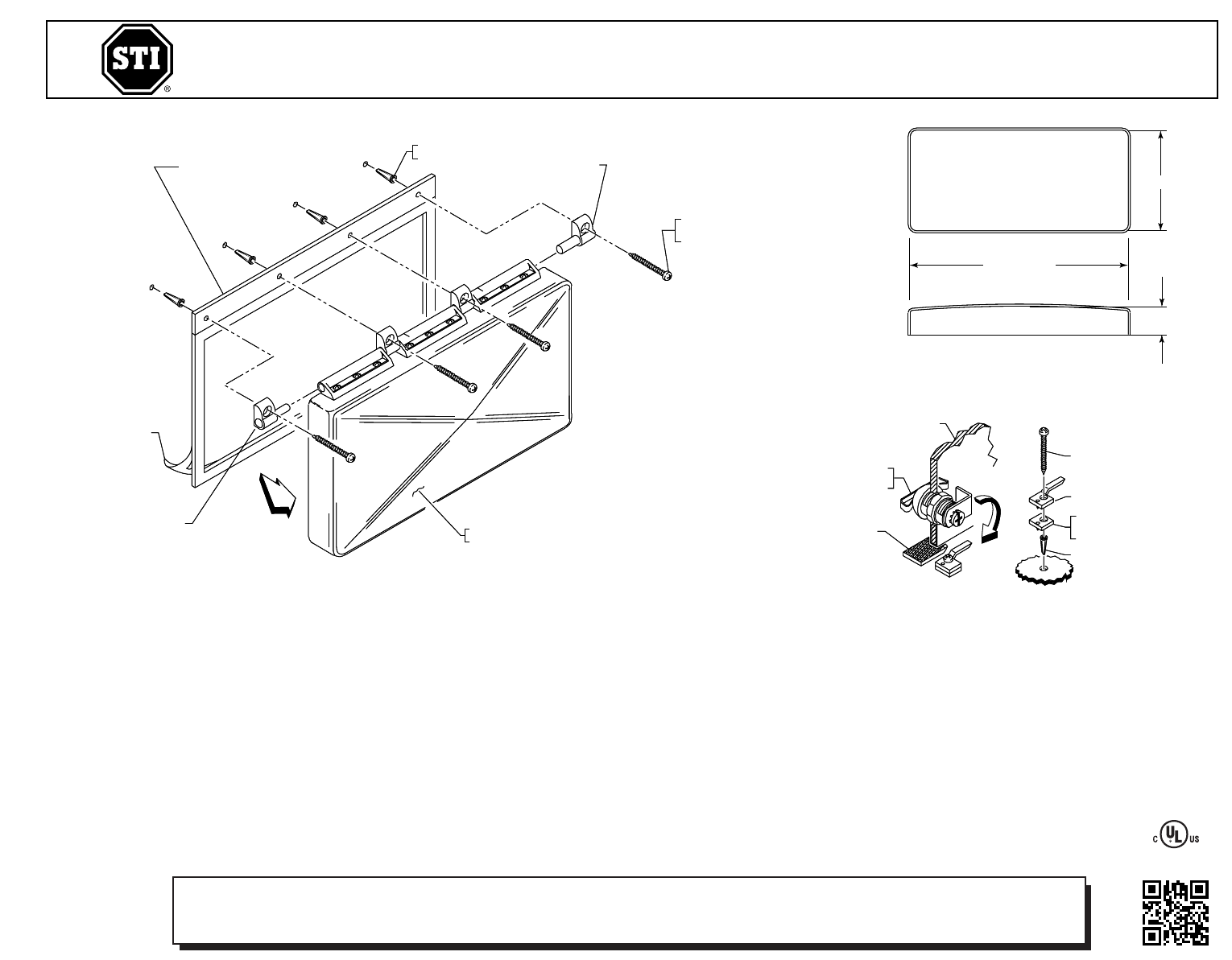
VIEW A
TOP VIEW
END VIEW
6 in.(152mm)
13 in.(330mm)
1.5 in.
(
38mm)
R
(CAM IS G ACING DOW
UNDER CAM LATCH (SEE VIEW A).
6
THE USE OF PROVIDED ANCHORS IS OPTIONAL.
C
(DO N OT SCRUB).
• RINSE ONCE MO
W ETTED THOROUGHLY
(DO N OT USE RAZOR BLADES).
I
GASKET
19018 ANCHOR
CAM LATCH
19039 SCREW
CUTAWAY SECTION OF COVER
07503 THUMB LOCK (SHOWN)
18050 KEY LOCK
(2) KEYS PROVIDED
LATCH SPACER (OPTIONAL)
DISCARD IF GASKET
IS NOT USED
PRODUCT DIMENSIONS
A
760099 GASKET (ADHESIVE BACKED)
19033 ANCHOR
(4) PROVIDED
RIGHT HINGE PIN
1
9013 SCREW
#10 x 1 1/2 in.
(4) PROVIDED
STI-7600 COVER ASSEMBLY WITH KEY LOCK
STI-7601 COVER ASSEMBLY WITH THUMB LOCK
LEFT HINGE PIN
REMOVE BACKING PAPER
INSTALLATION INSTRUCTIONS
1. Center cover over device to be protected.
2. Place a mark near the location of the cam latch.
3. Install cam latch and latch spacer if gasket is used.
4. Turn key or thumb lock to locked position (cam is facing downward,
see view A).
5. Place cover over device making sure cam is fully engaged under cam
latch (see view A).
6. Force cover against wall and mark mounting holes.
7. Remove cover and drill 3/16 in.(4.7mm) diameter holes.
8. Install gasket and cover assembly with screws provided. The use of
provided anchors is optional.
Safety Technology International, Inc.
2
306 Airport Road • Waterford, Michigan 48327-1209
Phone: 248-673-9898 • Fax: 248-673-1246
Toll Free: 800-888-4784 • E-mail: info@sti-usa.com
Web: www.sti-usa.com
Safety Technology International (Europe) Ltd.
U
nit 49G Pipers Road • Park Farm Industrial Estate • Redditch
W
orcestershire • B98 0HU • England • Tel: 44 (0) 1527 520 999
Fax: 44 (0) 1527 501 999 • Freephone: 0800 085 1678 (UK only)
E-mail: [email protected] • Web: www.sti-europe.com
INSTALLATION OF STI-7600 MEGA STOPPER
®
All specifications and information shown were current as of publication, and are subject to change without notice.
7600IS DEC2010
VIEW A
TOP VIEW
END VIEW
6 in.(152mm)
13 in.(330mm)
1.5 in.
(
38mm)
R
(CAM IS G ACING DOW
UNDER CAM LATCH (SEE VIEW A).
6
THE USE OF PROVIDED ANCHORS IS OPTIONAL.
C
(DO N OT SCRUB).
• RINSE ONCE MO
W ETTED THOROUGHLY
(DO N OT USE RAZOR BLADES).
I
GASKET
19018 ANCHOR
CAM LATCH
19039 SCREW
CUTAWAY SECTION OF COVER
07503 THUMB LOCK (SHOWN)
18050 KEY LOCK
(2) KEYS PROVIDED
LATCH SPACER (OPTIONAL)
DISCARD IF GASKET
IS NOT USED
PRODUCT DIMENSIONS
A
760099 GASKET (ADHESIVE BACKED)
19033 ANCHOR
(4) PROVIDED
RIGHT HINGE PIN
1
9013 SCREW
#10 x 1 1/2 in.
(4) PROVIDED
STI-7600 COVER ASSEMBLY WITH KEY LOCK
STI-7601 COVER ASSEMBLY WITH THUMB LOCK
LEFT HINGE PIN
REMOVE BACKING PAPER
Electronic warranty form at www.sti-usa.com/wc14
1
Summary of Contents
Page 1 - 7600IS DEC2010
Safety Technology International, Inc.2306 Airport Road • Waterford, Michigan 48327-1209Phone: 248-673-9898 • Fax: 248-673-1246Toll Free: 800-888-4784
Related products and manuals for Accessories for electrical Sti 7601
 (1 pages)
 (1 pages)
© 2020, manymanuals.com. All rights reserved. | 0.785 s |
 Manymanuals.com
 Manymanuals.de
 Manymanuals.fr
 Manymanuals.it
 Manymanuals.pl
 Manymanuals.cz
 Manymanuals.es
 Manymanuals-pt.com
Comments to this Manuals